Processing Overview
Brief overview of process steps and progression
4/6/202616 min read

As of the date of this post, I have made five frames. Throughout these five frames, I have experimented with different processes and construction methods, slowly refining to what I think is best for bikes made in a garage by a one man team. When I started this journey, I was a student at Georgia Tech; heavily involved in the Invention Studio makerspace; and had access to an EMCO E350 ~12" x ~8" x 8" 3-axis CNC mill w/ toolchanger, Tormach PCNC 1100 18" x 9.5" x 16.25" 3-axis CNC mill, large CAMMaster Cobra router, a knee mill, and an engine lathe. Although not the fanciest of machine tools, I used them extensively and took advantage of only paying for materials for CNC machined parts. After bike ~3.5, I graduated and no longer had access to these tools and have had to make some changes to my workflow to accomodate. Currently, my main workhouse tools are a Sieg X2D mini mill, Bambu Lab H2S printer, a freezer, a homemade filament winder, and an Arduino-hacked, used home oven. I am shopping for lathes at the moment and day dream about having a CNC mill of my own. Machine tools are no doubt great, but you can make some very high quality, complex composite parts with a 3D printer and a cheap oven.
I obviously would love to be able to make an entire bike frame as one part. It would simplify many steps of the process and make a stiffer, lighter bike. That being said, I did not have access to a CNC mill capable of making metallic molds that large, do not have the equipment to handle a metallic mold that large and heavy, and do not have an oven large enough to cure a part that large. As a result, I have accepted making frames in multiple parts and bonding together. There are some benefits to this process including: frame alignment comes from the accuracy of my frame jig, not my molds; if designed well, I have some level of modularity and adjustability of size; layups are less expensive, lower risk, and more simple; and possibility of reusing some parts between different frames. Although modern carbon bikes are referred to as 'monocoque,' this is generally a lie. The majority of carbon bikes these days are made as a front triangle, chainstays, and seatstays (dropout likely on one of the stays) and bonded together. We are seeing a couple of frames made as one piece these days, but they tend to be only the most expensive ones from a few companies (the innovation here is coming from certain East Asian manufacturers, not western bike brands). Some very nice bikes are even made of multiple parts in the front triangle too these days.
There are many different manufacturing processes for composite parts, with a variety of complexity, capability, and equipment/tooling requirements. Fundamentally, a good composite part needs well aligned fabric trapped in a resin/matrix that is free of voids. To achieve this, you need to be able to cleanly apply the fabric, infuse with a consistent amount of resin, and cure under compression such that air trapped during layup and generated from the curing process is driven out of the part. The challenge of composites is (1) How can I make a rigid mold that defines the shape of the part in the places that I want and (2) How can I apply pressure to the part so that it is driven into the mold and porosity is minimized. Most bicycle frames are made with female clamshell molds on the outer mold line (OML) and a flexible bladder on the inner mold line (IML). This is not standard in the greater composites industry; very few composite parts are hollow, tube-like structures where surface quality of the OML is critical. Yes, there are a lot of poorly made carbon bikes out there and bicycles are not the most high-tech industry, but a bicycle frame is actually a very complex composite part to make. This approach to making parts is not the cheapest as it requires investments in tooling, but I think it is worth it and I think I have a workflow that makes it more approachable than a $10,000+ metallic mold.
Fabric and resin can be purchased in many different ways. I won't get too much into it here because there are a lot better resources that already exist explaining this. I have experimented with wet layup before I started on frames and think it is painfully clunky and limiting for bike parts. Pre-preg, which is the industry standard, is extremely powerful and not as daunting as it appears. Filament winding is awesome but not without limitations.
Construction Style History:
Frame 1: (5/2022-2/2023)
Fully prepreg molded
"Mid" tube bonded lap joints
Pros:
Fewer parts, less redundant weight
Bond joints away from higher stress locations
Cons:
$$$ molds for one size and one size only
Very difficult to reuse some parts/molds in future frames
Frame 2: (8/2023-11/2023)
Filament wound (minus chainstays)
Tube-tube construction, bonded and overwrapped joints
Pros:
Almost all molds are reusable for 48->62 frame (minus head tube (HT))
Lower mold cost
Cons:
Less control over frame shape
Especially at tube junctions
Overwrapping cleanly is difficult
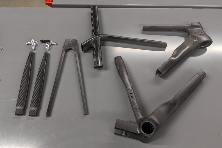
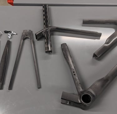
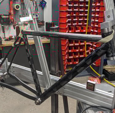
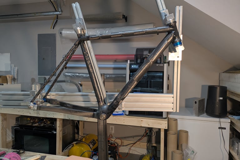
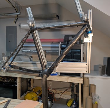
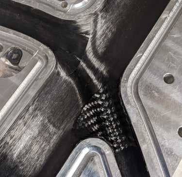
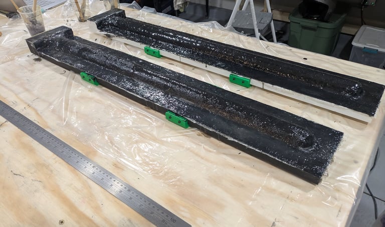
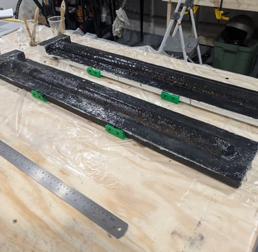
Frame 3-5: (8/2023-Current)
Mix of prepreg molded “lugs” and filament wound tubes (mostly)
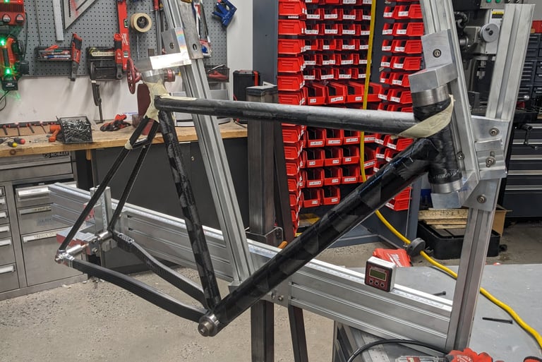
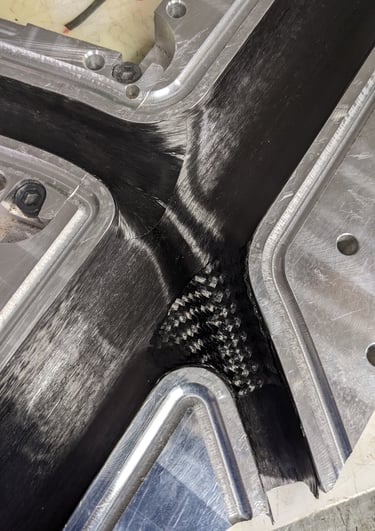
Frame to the right isn't the perfect example since the Down Tube (DT) -
Top Tube (TT) - HT joint is mitered and overwrapped
Tube end bonded lap joints
Pros:
Shape control of prepreg with size modularity of tube-tube (within reason)
Cheaper mold cost relative to full prepreg
Parts/molds can be reused from frame to frame more easily
Cons:
Lots of parts and molds for one frame
Weight penalty with so many bonded joints
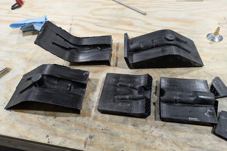
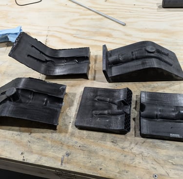
I have experimented with making molds now by 3D printing ASA CF plugs and making tooling prepreg molds off of them. Tooling prepreg molds off of 3D printed parts are cheaper but have a ceiling with tolerances. They're also not as much cheaper as you would expect from a materials perspective, but a lot cheaper than paying for CNC time. The main worry about these molds is tolerances. Most parts of the bike do not require high tolerances so most of the time this is not an issue. I would say general surface tolerance is probably +/- 1mm before you notice, bonding interface tolerance is probably +/-0.5mm.
Bearing alignment is the one place where things start to matter, both HT and bottom bracket (BB).
Cylindricity for a single side (e.g. lower HT race, right BB race) is solvable by using machined aluminum pucks. These are easy to make with a lathe or cheap to outsource via PCBway (or similar). Obviously there are some risks of using an aluminum insert with much higher thermal expansion coefficients than the composite tooling, however I have not had issues with it yet. I have found the thermal expansion of the pucks to actually be beneficial when demolding because the carbon is cured in the expanded shape of the puck. This does mean that you have to machine the pucks slightly undersized to spec so they hit spec at temp.
Alignment is less easy to solve.
For the BB, your bearing alignment is coming down to a massive tolerance stack up between the two sides of the mold half. The simplest way to solve this is bonding in a BSA or T47 shell into the frame. Paragon Machine Works (rip) used to make fantastic titanium shells already to thread and width spec with grooves on the outside for increased surface area. When they shut down, I frantically bought $500 worth of shells to have stock. I will be keeping an eye out on new suppliers for this.
For the HT, I am still figuring out what the best path forward is. To be honest, I have yet to attempt a tooling prepreg heat tube mold. I have been very hesitant that there is a good way forward. You could always bond in custom inserts (I believe Argonaut does this), but I think this is a little clunky and would likely require a precise fixture. All of that being said, I am starting to think you can get away with more here than I have been giving credit, ultimately bearings are a little overkill for their use case in the HT, it is not spinning fast nor high cycle. When I do make a HT mold, I will make sure to post something about it.
Layup methods
I currently prefer the double C approach where all of the prepreg is laid up on the two the mold halves with a lap extending proud from one side. Closing the mold can be a little awkward to ensure the proud laps do not get trapped where they shouldn't be however I have a simple process to almost entirely eliminate this.
The main downside is that it is harder to get fibers laid down for hoop and torsion because they need to cross the split line. There are also some plies that are harder to apply since you are working inside a cavity instead of a protrusion.
The main benefit is that there is negligible fiber distortion. The plies are extremely close to their final position, so they won't shear and wrinkle unexpectedly. This is helpful from a design perspective because you can be confident that the carbon is reasonably close to design. A strip of UD that makes an S-curve will not be as stiff as it was straight in FEA.
Almost every carbon frame made in East Asia is instead made by applying prepreg plies to the bladder. I would guess that the main reason for this is actually so that a mold is not tied up for the entire layup process, only for the curing process. That being said, if you can place the plies down close to the final position, there are layups you can achieve that you couldn't with the double C approach. Placing the plies close to the final position is harder than you would expect. In my opinion, the bladder is already the hardest part of the process. There are not many good processes for making thin walled, flexible, variable, and tubular parts that can handle elevated temperatures. Adding the design requirement that they need to have a surface tolerance of +/-1mm and you have a complex problem. There is a reason most companies don't offer raw carbon frames, they struggle with this too. Their frames have high spots, low spots, and wrinkling all exacerbated by the fact most bikes are made from plies <0.2mm thick. Most of this comes back to the plies not being able to move enough from their layup position to final target position. There is considerable development being invested into this to create lower cost solutions, and is partially why we are seeing lighter and lighter frames. The designers know that all their plies are actually staying in the part and functional, and are not just being sanded off. Now that I am getting more refined and reliable bladders, I plan on experimenting with laying up at least partially on the bladder.
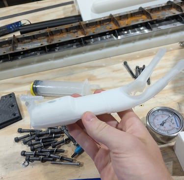
Internal pressure bladder
Pressure is critical! Traditional composite processes happen under vacuum, which will get you all of 14.7psi. Autoclaves normally start around 100psi and easily go up to 300. Obviously more pressure is almost always better, however there is a point of diminishing returns. In my experience, my goal is to hit 60-75 psi. Greater than 60 psi, I have visually noticed a drop in porosity. Making good bladders has been a challenge, so I rarely risk pushing higher than 75 psi. For aluminum molds, the pressure has not been enough to cause deformation, however I am starting to notice that I need to stiffen the composite molds in some places to handle 75 psi without deforming beyond acceptable.
If I were to summarize my experience so far, I would say that the actual challenge to making good bicycle frames and parts is making good bladders and end fittings.
For simple tubes (chainstays and some others) standard tubular bag film is acceptable but can lead to wrinkles (generally just resin rich not poor compaction). There is however an art form to terminate these tubular bags if one end has to terminate inside the part. I am starting to get this down and it requires folding in extra length to ensure it can expand "axially."
For joints or Y shaped parts, I have iterated a lot on custom bladders. I think custom bladders are worth the effort investment. It can be very difficult to pack a tubular bag inside of a BB cluster with shootouts for the DT, ST, and CS's and ensure that it expands sufficiently everywhere. Tubular bags are not stretchy so they are unforgiving, enough extra needs to be bunched or folded in. For the custom bladders I have worked with both latex and silicone.
I started with a poor attempt at silicone using a brush on Vac-Bag Smooth On silicone that scared me away to latex. It was very difficult to apply thin layers and seemed to have poor tear strength.
A lot of the bladders in the bike industry are made out of latex by Piercan and can handle a couple of runs at elevated temperature. Working with a latex that can handle higher temperatures in a home shop while not being a materials engineer has been very difficult. I worked with multiple different Holden's Latex models, trying both dipping and brushing. I would either machine a foam core or 3D print a PVA core and slowly apply layers until I was happy with the thickness. My girlfriend did not appreciate my gallon containers of liquid latex dissolved in ammonia in our apartment between graduating GT and having a garage. It was a slow process that was more art than engineering that resulted in a good bladder probably 50% of the time. I made it work for a while because I was too daunted to take a jump to silicone or other and start over.
Between bike 4 and 5, I realized it was time to give silicone another shot. My goal was to instead cast/inject it into a clamshell mold with a core to get the hollow structure. This has worked very well and I regret not trying it earlier. There is more time in CAD spent designing another mold for every part, however I can now remake a bladder in 12 hrs instead of a couple days and I have yet to have an issue with them popping due to heat and pressure during the cure. I am experimenting with different ways of injecting the silicone and if using vacuum helps, but am not entirely sure yet. I use Smooth On Dragon Skin 20 currently and it seems like a good balance of viscosity, elasticity, and strength. The core is made with either PVA or PLA depending on how "trapped" it is and is removed before layup. Making these silicone bladders is the step I needed to take to start experimenting with either full or partial layup on it instead of the mold. I now have complete control over its shape and can make them quickly.
I am still iterating and perfecting the sealing plug interface between the bladder and the rigid part I can plug a quick disconnect into. I will go into more detail in a future blog, however I use tapers (and tapers with orings for the tubular bags) with fasteners to wedge in the seal. Realistically, I would like to make a "universal" taper assembly that I can bolt up to different molds, but I am still working on that.
I have not tried thermal expansion silicone methods, but I have some hesitancy. I was lucky enough to talk with an engineer from Argonaut the first year of the Made bike show and he said that they currently spend more money on silicone than carbon because of how much they use to make the solid plugs. Needless to say, that scared me away.
Suppliers
I have not experimented with many different prepreg suppliers. It is difficult to play the game as one person in their garage. I have purchased a lot from Easycomposites and I think they have good enough prepreg (part and tooling). It is pretty low cost and low MOQ. It is no Toray T1100 fiber but I like their XC130 line and have gotten good results with it even though it technically says autoclave only. I use a mix of the 210gsm 2x2, 300gsm UD, and 150gsm UD. On my first frame I used some of the 88gsm spread tow. Spread tow looks awesome (and is critical for some applications, it is pretty much the only fabric I can use for my parts at work), but it has poor drapability which is critical for the complex curvatures you get on bike frames. The XC130 is a 250F cure system resin so it is easy to process in a modified home oven. The XT135 tooling prepreg resin can be gelled at a temp the ASA CF can handle and still be post cured to handle the 250F cure.
It would be great to use nicer fabrics and resins, and I hope to use some work connections to start conversations with the right people in the future, but at the moment this is not my biggest hurdle to making better bikes.
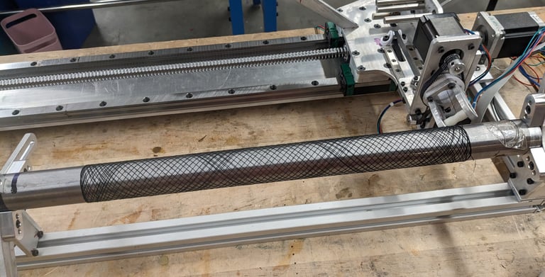
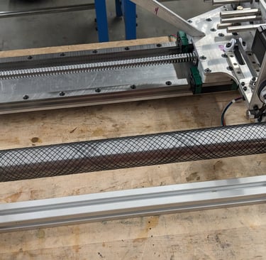
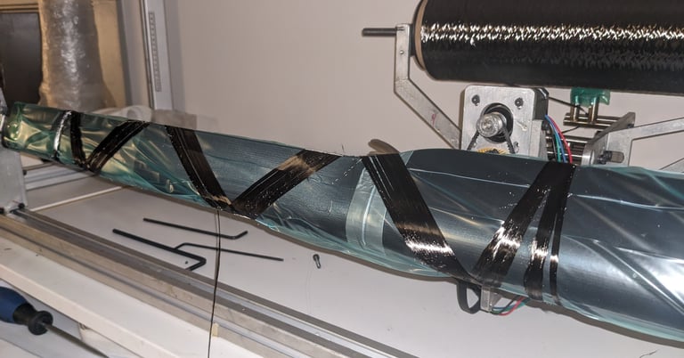
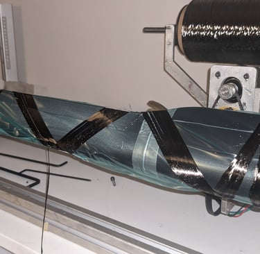
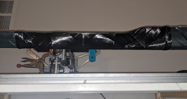
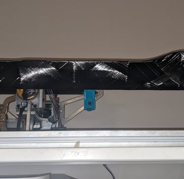
Overview of my filament winding process:
Filament winder/winding
I made my own filament winder summer through fall of 2023, both the machine and the "CAM" code. It is similar to the X-winder, better in some and worse in others. It is currently designed and programmed to do straight, round tubes but I have found that it is still pretty capable at doing more complex stuff. I have told myself for 2 years now that I will update the code and machine to handle much more, but I keep putting it off because it has been good enough for what I have needed so far. Filament winding is awesome. It allows for consistent layup of tubular structures while I am doing other things. That being said, it isn't perfect.
Pros:
Pretty consistent parts easily
Great torsional and hoop strength parts because of the continuous fiber
The main benefits are logistical though
My oven is not large enough to handle molds long enough for a full DT. Since I can use a 2 part epoxy, I can cure at room temp.
I did/do not have access to a CNC mill with X travel long enough for a full DT mold, meaning that I did not have great options for making molds that could handle elevated temperatures even if I solved the oven size problem.
Cons:
Tube geometry has limits because of how well the fiber gets wrapped around. There is a very fine balance to get the right fiber tension such that it lays well and does not slip over complex shapes (transitions or truncated airfoils).
The layup can only be so optimized because it ends up being pretty much uniform and it is hard to lay fabric down at less than a 15 degree angle. With prepreg, you can easily reinforce certain higher stress areas. I have started to get around the lack of axial fabric by manually placing UD plies at some point of the stack up, but it is not foolproof because dry UD fabric options are not as good as prepreg.

Mold styles
As touched on earlier, one side needs to be tooling/rigid surface and one side needs to apply compaction. The majority of filament winding uses a male tooling surface, where the rigid side is on the IML. Logically, it makes the most sense since you already need a rigid mandrel to wrap around during the filament winding process. That being said, it can cause issues with compaction. All layups have a bulk factor. It is realistically impossible to layup a part straight to its target thickness and compaction. With a male tooling surface, your bulk factor means that your later plies wrap a larger diameter than they could once compacted. This then means they have a longer circumference. Especially noticeable on filament winding where the "plies" wrap the full circle multiple times, once you compress the stackup, that extra length generally has to go somewhere and carbon fiber tow doesn't shorten in length before it wrinkles. Wrinkly carbon fiber does not make strong nor stiff parts. The easiest way around this is to wind with a lot of excess resin, apply some but not too much compression, and hope that the excess resin fills all of the gaps. Although na OML approach to filament winding is not the easiest, hopefully you can see why it is desirable.
Male tooling surface
Wind around a rigid mandrel
Vacuum bag or shrink tape to compress it down to mandrel
Pros:
Super cheap mold/mandrel (can literally use stock McMaster aluminum tubes
Cons:
Getting good exterior surface can be artform (visual problem, less structural)
Very limited tube shapes
Female tooling surface
Wind around a removable mandrel
Replace mandrel with tubular bag
Tubular bags are more than acceptable since they are generally simple shapes. I do not make my life even harder and make custom bladders for these too.
Place inside a clamshell mold
Originally I machined molds out of UHMW on a large wood router. It was ok. The wood router was pretty tired and that was the bigger problem.
I have tried to make a composite tool, first 3D printing a plug with PVA and then making a fiberglass and polyurethane mold. Apart from having to work with chopped strand mat and the smell of polyurethane, it worked very well. I plan to continue this going forward, just with carbon fiber/ woven fiberglass and tooling epoxies. It will be worth the extra cost.
Inflate to expand to tooling surface
Pros:
Much less limited tube shapes
Great exterior surface
Better compaction (60psi > 14.7psi or tape tension)
Stretching fiber better than compressing fiber during cure
Cons:
Mold is more expensive but not necessarily machined aluminum expensive
So that is pretty much everything I have learned over the past four years summed up, at least from the manufacturing side. There's some finer details that I did not touch on like surface modelling manufacturable parts; FEA and layup design; specifics of aluminum mold design; 3D printed plug prep for tooling prepreg; and inserts, interfaces, and bonding. I have also made a couple handlebars and triathlon extensions. They have some of their own unique challenges, but ultimately are very similar to what I touched on for the frames above. I will work on posting new blogs with some consistency. If you have any specific questions, please don't hesitate to reach out. If it isn't obvious by now, I like sharing what I have learned, talking about bikes, and how to make things.
Overview of my prepreg molding process:
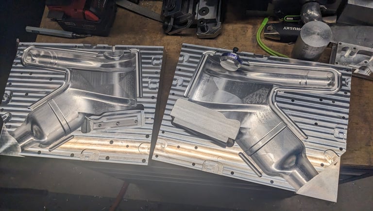
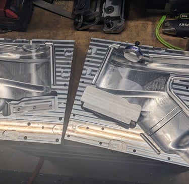
OML Mold
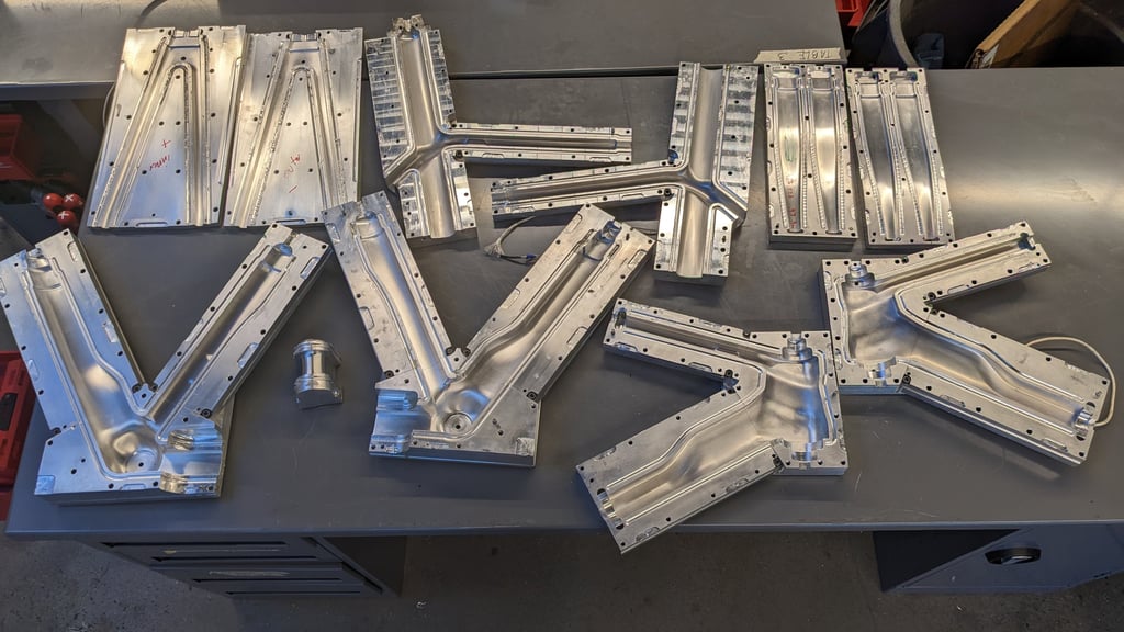
I started with machined aluminum molds while at Tech because they are precise, reusable, and comparatively cheap when you're not paying for labor and machine time.
The track frame was a minimum of $2,500 in aluminum for molds, but it has many parts and a fork. Yes, that is a lot of money but I do not have to remake a mold if my first attempt at the part has pressure or layup problems. The first prepreg part I made for frame #1 took me 10 tries before I was happy. The mold still looks new (not the same mold as pictured below).
sixty four cycles
Atlanta, GA
7038211149
iain@64cycles.com